Resistance
Storyboard 
The flow around a wing leads to the formation of whirlpools that, depending on the shape and angle of the wing with respect to the flow, can cause whirlpools in a section of these. If volume elements around the wing are considered and it is assumed that energy conservation can be madly assumed, different speeds will have to lead to different pressures (Bernoulli) on the surface.
The sum of all pressures on the surface in the direction of flight, both in front of the wing (backward force) and behind the wing (forward force) leads to a total force that we call resistance. To be able to propel a body (airplane / bird) it is necessary for the propulsion to overcome this resistance force.
ID:(464, 0)
Resistance
Storyboard
The flow around a wing leads to the formation of whirlpools that, depending on the shape and angle of the wing with respect to the flow, can cause whirlpools in a section of these. If volume elements around the wing are considered and it is assumed that energy conservation can be madly assumed, different speeds will have to lead to different pressures (Bernoulli) on the surface. The sum of all pressures on the surface in the direction of flight, both in front of the wing (backward force) and behind the wing (forward force) leads to a total force that we call resistance. To be able to propel a body (airplane / bird) it is necessary for the propulsion to overcome this resistance force.
Variables
Calculations
Calculations
Equations
The lift force ($F_L$), along with the wing span ($L$), the density ($\rho$), the wing top speed factor ($c_t$), the wing bottom speed factor ($c_b$), the upper wing length ($l_t$), the bottom wing length ($l_b$), and the speed with respect to the medium ($v$), is found in
If we consider the surface that generates lift ($S_w$), given by the wing span ($L$), the upper wing length ($l_t$), and the bottom wing length ($l_b$),
and for the coefficient of lift ($C_L$), defined as
we obtain
Similarly to how the equation for the lift force ($F_L$) was derived using the density ($\rho$), the coefficient of lift ($C_L$), the surface that generates lift ($S_w$), and the speed with respect to the medium ($v$)
in this analogy, what corresponds to the surface that generates lift ($S_w$) will be equivalent to the total object profile ($S_p$) and the coefficient of lift ($C_L$) to the coefficient of resistance ($C_W$), thus the resistance force ($F_W$) is calculated:
The drag coefficient is measured and, in turbulent flows over aerodynamic bodies, values are generally found around 0.4.
Using the relationships of the total resistance force ($F_R$) with the lift force ($F_L$), the resistance force ($F_W$), and the angle of attack of a wing ($\alpha$):
we can calculate using the resistance force with the density ($\rho$), the coefficient of resistance ($C_W$), the total object profile ($S_p$), and the speed with respect to the medium ($v$):
and the lift force with the surface that generates lift ($S_w$) and the coefficient of lift ($C_L$):
using the relationship for the coefficient of lift ($C_L$) with the proportionality constant coefficient sustainability ($c$):
using the relationship for the sine of the small angle of attack $\alpha$:
and the cosine:
with the condition to balance the weight of the bird or aircraft for the body mass ($m$) and the gravitational Acceleration ($g$):
we obtain:
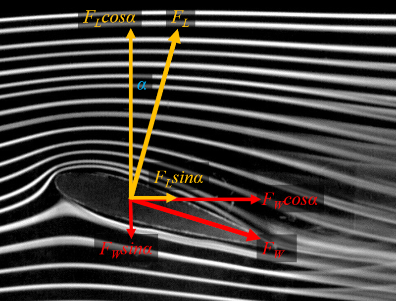
The horizontal component of the lift force corresponds to the force $F_L$ multiplied by the sine of the angle of attack $\alpha$:
$F_L \sin\alpha $
And the horizontal component of the drag force corresponds to the force $F_W$ multiplied by the cosine of the angle of attack $\alpha$:
$F_W \cos\alpha $
Therefore, the total resistance force can be calculated as:
The sine can be calculated using a polynomial of the form:
$\sin \alpha = \alpha - \displaystyle\frac{1}{3!}\alpha^3 + \displaystyle\frac{1}{5!}\alpha^5 \ldots$
For small values of the angle of attack of a wing ($\alpha$) ($\alpha \ll 1$), the terms with higher powers are negligible, and we obtain:
The cosine can be calculated using a polynomial of the form:
$\cos \alpha = 1 - \displaystyle\frac{1}{2!}\alpha^2 + \displaystyle\frac{1}{4!}\alpha^4 \ldots$
For small values of the angle of attack of a wing ($\alpha$) ($\alpha \ll 1$), the terms with higher powers are negligible, and we obtain:
Examples
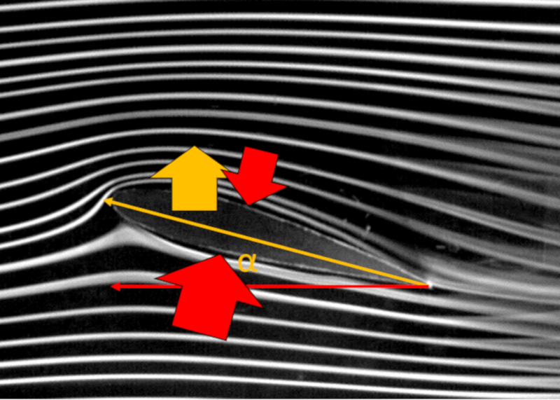
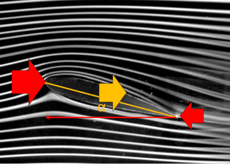
Upon observing the average flow around a wing, one can notice that the lines above the wing are longer than those below it. In simplified terms, it is argued that due to this longer path, the speed at the top ($v_t$) is expected to be greater than the speed at the bottom ($v_b$), although both are higher than the speed with respect to the medium ($v$).
If Bernoulli's law is applicable, the difference in velocities would result in a difference in pressures acting on the wing. In particular, if the speed at the top ($v_t$) is greater, its corresponding the pressure on top of wing ($p_t$) would be lower than with the speed at the bottom ($v_b$) and its corresponding the pressure on the bottom of the wing ($p_b$). This would imply the existence of a the lift force ($F_L$) due to the effect of this pressure difference.
However, as seen towards the end of the wing profile (right side), turbulence forms, limiting the applicability of Bernoulli's principle. Specifically, it should be considered that in a certain portion of the wing's perimeter, it may not be applicable, and there will be no contribution to lift.
The object not only generates lift but also creates resistance to the airflow in its surroundings. While the direct application of Bernoulli's principle may not be feasible, we can still understand the kind of effect to expect, even if it needs to be modeled differently. In this context, at the wingtip, the velocity is zero, leading to maximum pressure. Similarly, at the trailing end of the object, the velocity is at its maximum, resulting in minimum pressure. This generates pressure opposing the object's forward motion, corresponding to resistance.
However, it's crucial to note that this argument is only partially correct. In particular, turbulence is generated at the wing's trailing edge, which complicates the high-speed argument and challenges the application of Bernoulli's principle.
Following the modeling approach used for lift, we can assume that the Kutta-Joukowski theorem, in which the lift force ($F_L$) with the density ($\rho$), the speed with respect to the medium ($v$), and the aerodynamic circulation ($\Gamma$), is:
We can assume it to be vectorial, meaning it has a vertical component explaining lift and a horizontal component modeling resistance.
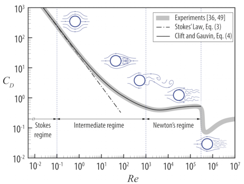
The coefficient of resistance $C_d$ is often a function of the Reynolds number $Re$. In the case of a sphere, the coefficient of resistance takes the form:
In the range of low Reynolds numbers, the coefficient of resistance is inversely proportional to the velocity $1/v$, which means that in this range, the drag force is proportional to the velocity (Stokes' law).
In the range of high Reynolds numbers, the coefficient of resistance becomes constant, resulting in a drag force that is proportional to the square of the velocity. However, it is important to note that there is a sudden drop in the coefficient, indicating a situation where the turbulent zone decreases.
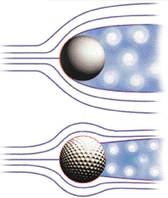
If the goal is to reduce the resistance of a ball, it is necessary to increase the Reynolds number to take advantage of the decrease in the coefficient of resistance. This can be achieved by introducing grooves, such as those found on a golf ball. These grooves act as small dividers that keep the layer of air attached to the ball, allowing the flow to remain more linear for a longer period of time and reducing the area that generates resistance.
When the wing is tilted, it not only generates lift but also produces a component of drag, as the direction of lift is orthogonal to the wing's surface. If we graph the lift force ($F_L$), the resistance force ($F_W$), and the angle of attack of a wing ($\alpha$), we obtain:
From the works of Kutta [1] and Joukowski [2], a theorem was developed that shows the association between the aerodynamic circulation ($\Gamma$) and the lift force ($F_L$) through the wing span ($L$), the density ($\rho$), and the speed with respect to the medium ($v$) as follows:
[1] " ber die Aufgabe der Fl geltheorie und ein neues Verfahren zur Herleitung derselben." (On the task of wing theory and a new method for its derivation.), Martin Wilhelm Kutta, Nachrichten von der Gesellschaft der Wissenschaften zu G ttingen, Mathematisch-Physikalische Klasse (1902)
[2] " ber die Erhaltung des Luftkreises um ein Profil." (On the conservation of the air circle around a profile.), Nikolai Zhukovsky, Nachrichten von der Gesellschaft der Wissenschaften zu G ttingen, Mathematisch-Physikalische Klasse (1904)
To generate higher pressure below than above the wing and generate lift, Bernoulli's principle is employed, correcting for the lack of energy density conservation using ERROR:6119.1. The pressure over the wing, the lift force ($F_L$), can be estimated using the density ($\rho$), the surface that generates lift ($S_w$), the coefficient of lift ($C_L$), and the speed with respect to the medium ($v$) through the following formula:
The resistance force ($F_W$) kann mit the density ($\rho$), the coefficient of resistance ($C_W$), the total object profile ($S_p$) und the speed with respect to the medium ($v$) entsprechend berechnet werden folgende Formel:
The total force of resistance is composed of the horizontal components of the wing profile's resistance force $F_W$ and the lift force $F_L$, which can be calculated from the angle of attack $\alpha$:
From measurements, it is concluded that the lift coefficient $C_L$ is proportional to the angle of attack $\alpha$:
After a certain angle, the curve decreases until it reaches zero. This is because beyond that critical angle, the vortices fully cover the upper surface of the wing, leading to a loss of lift. This phenomenon is known as \"stall\".
For small angles, the sine function can be approximated by a straight line that passes through the origin. If the angle of attack of a wing ($\alpha$) is expressed in radians, the slope of this line is equal to one, and we get:
For small values of the angle of attack of a wing ($\alpha$), the cosine function can be approximated by an inverted parabola that passes through the origin. If the angle is expressed in radians and is approximately zero, we get:
To calculate the total resistance force ($F_R$), we assume small angles and consider a situation where the angle is such that it maintains the body mass ($m$). Using this approximation and the variables the coefficient of lift ($C_L$), the coefficient of resistance ($C_W$), the surface that generates lift ($S_w$), the total object profile ($S_p$), the gravitational Acceleration ($g$), the proportionality constant coefficient sustainability ($c$), the density ($\rho$), and the speed with respect to the medium ($v$), we obtain the following expression:
ID:(464, 0)