
Movimeinto de Gases
Description 
Variables
Calculations
Calculations
Equations
(ID 939)
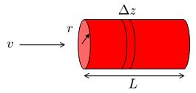
If we consider the profile of ERROR:5449,0 for a fluid in a cylindrical channel, where the speed on a cylinder radio ($v$) varies with respect to ERROR:10120,0 according to the following expression:
| $ v = v_{max} \left(1-\displaystyle\frac{ r ^2}{ R ^2}\right)$ |
involving the tube radius ($R$) and the maximum flow rate ($v_{max}$). We can calculate the maximum flow rate ($v_{max}$) using the viscosity ($\eta$), the pressure difference ($\Delta p$), and the tube length ($\Delta L$) as follows:
| $ v_{max} =-\displaystyle\frac{ R ^2}{4 \eta }\displaystyle\frac{ \Delta p }{ \Delta L }$ |
If we integrate the velocity across the cross-section of the channel, we obtain the volume flow ($J_V$), defined as the integral of $\pi r v(r)$ with respect to ERROR:10120,0 from $0$ to ERROR:5417,0. This integral can be simplified as follows:
$J_V=-\displaystyle\int_0^Rdr \pi r v(r)=-\displaystyle\frac{R^2}{4\eta}\displaystyle\frac{\Delta p}{\Delta L}\displaystyle\int_0^Rdr \pi r \left(1-\displaystyle\frac{r^2}{R^2}\right)$
The integration yields the resulting Hagen-Poiseuille law:
| $ J_V =-\displaystyle\frac{ \pi R ^4}{8 \eta }\displaystyle\frac{ \Delta p }{ \Delta L }$ |
(ID 3178)
The volume flow ($J_V$) can be calculated from the hydraulic conductance ($G_h$) and the pressure difference ($\Delta p$) using the following equation:
| $ J_V = G_h \Delta p $ |
Furthermore, using the relationship for the hydraulic resistance ($R_h$):
| $ R_h = \displaystyle\frac{1}{ G_h }$ |
results in:
| $ \Delta p = R_h J_V $ |
(ID 3179)
One way to model a tube with varying cross-section is to divide it into sections with constant radius and then sum the hydraulic resistances in series. Suppose we have a series of the hydraulic resistance in a network ($R_{hk}$), which depends on the viscosity ($\eta$), the cylinder k radio ($R_k$), and the tube k length ($\Delta L_k$) via the following equation:
| $ R_h =\displaystyle\frac{8 \eta | \Delta L | }{ \pi R ^4}$ |
In each segment, there will be a pressure difference in a network ($\Delta p_k$) with the hydraulic resistance in a network ($R_{hk}$) and the volume flow ($J_V$) to which Darcy's Law is applied:
| $ \Delta p = R_h J_V $ |
the total pressure difference ($\Delta p_t$) will be equal to the sum of the individual ERROR:10132,0:
| $ \Delta p_t =\displaystyle\sum_k \Delta p_k $ |
therefore,
$\Delta p_t=\displaystyle\sum_k \Delta p_k=\displaystyle\sum_k (R_{hk}J_V)=\left(\displaystyle\sum_k R_{hk}\right)J_V\equiv R_{st}J_V$
Thus, the system can be modeled as a single conduit with the hydraulic resistance calculated as the sum of the individual components:
| $ R_{st} =\displaystyle\sum_k R_{hk} $ |
(ID 3180)
The parallel total hydraulic conductance ($G_{pt}$) combined with the hydraulic conductance in a network ($G_{hk}$) in
| $ G_{pt} =\displaystyle\sum_k G_{hk} $ |
and along with the hydraulic resistance in a network ($R_{hk}$) and the equation
| $ R_h = \displaystyle\frac{1}{ G_h }$ |
leads to the total hydraulic resistance in parallel ($R_{pt}$) via
| $\displaystyle\frac{1}{ R_{pt} }=\sum_k\displaystyle\frac{1}{ R_{hk} }$ |
(ID 3181)
(ID 3469)
(ID 3624)
Since the hydraulic resistance ($R_h$) is equal to the hydraulic conductance ($G_h$) as per the following equation:
| $ R_h = \displaystyle\frac{1}{ G_h }$ |
and since the hydraulic conductance ($G_h$) is expressed in terms of the viscosity ($\eta$), the tube radius ($R$), and the tube length ($\Delta L$) as follows:
| $ G_h =\displaystyle\frac{ \pi R ^4}{8 \eta | \Delta L | }$ |
we can conclude that:
| $ R_h =\displaystyle\frac{8 \eta | \Delta L | }{ \pi R ^4}$ |
(ID 3629)
(ID 3632)
(ID 4257)
(ID 4502)
(ID 4833)
(ID 4834)
Examples
If one observes a
(ID 7019)
A section change can be represented by two radio tubes
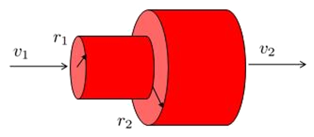
which leads to the initial speed
(ID 7020)
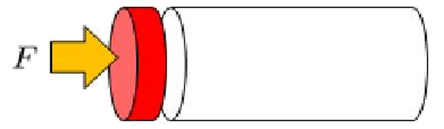
To show how the volume element is pushed by a tube we must consider a force
(ID 7023)
The element in the tube is exposed to the pressures of both ends:
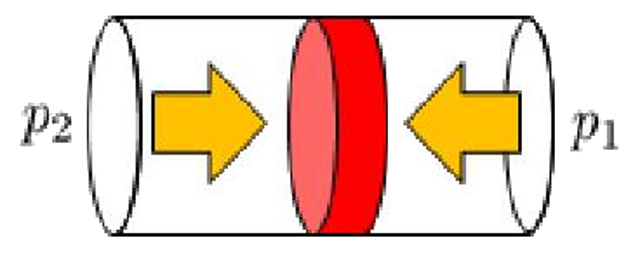
so that it moves according to either of the two pressures exceeds the other in the direction of the lowest pressure.
(ID 7024)
ID:(731, 0)