Two springs in series
Quote 
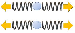
If you want to model how a solid deforms under the influence of a force, you can first consider the behavior of a subunit, such as two springs connected one behind the other, as shown in the image:

This type of arrangement of the springs is called in series. It is characterized by the fact that the force the force ($F$) is the same in both springs, and they deform according to the hooke Constant ($k$). Therefore, the equivalent spring constant the elongation ($u$) is calculated as the sum of the spring elongation 1 ($u_1$) and the spring elongation 2 ($u_2$), which, in turn, by Hooke's law:
| $ F_k = k u $ |
is equal to the force ($F$) divided by the constants the spring Hook constant 1 ($k_1$) and the spring Hook constant 2 ($k_2$), respectively:
$u = u_1 + u_2 = \displaystyle\frac{F}{k_1} + \displaystyle\frac{F}{k_2} = \left(\displaystyle\frac{1}{k_1} + \displaystyle\frac{1}{k_2}\right)F$
Therefore, the system of two springs can be treated as a single spring whose equivalent spring constant the total Hook constant of springs in series ($k_s$) is calculated as follows:
| $\displaystyle\frac{1}{ k_s }=\displaystyle\frac{1}{ k_1 }+\displaystyle\frac{1}{ k_2 }$ |
ID:(1910, 0)
Two Springs in Parallel
Exercise 
If one wishes to model how a solid deforms under the influence of a force, the behavior of a subunit can first be considered, such as two springs connected side by side, as shown in the image:

This type of arrangement of the springs is called in parallel. It is characterized because the elongation ($u$) in both springs is the same and each spring contributes the force ($F$) according to the spring Hook constant 1 ($k_1$) and the spring Hook constant 2 ($k_2$) as per Hooke's law:
| $ F_k = k u $ |
Thus, it follows that:
$F = F_1 + F_2 = k_1 u + k_2 u = (k_1 + k_2)u$
Therefore, the system of two springs can be treated as a single spring whose equivalent spring constant the total Hook constant of springs in parallel ($k_p$) is calculated as follows:
| $ k_p = k_1 + k_2 $ |
ID:(1692, 0)
Sum of multiple springs in parallel
Equation 
In the case of two springs with constants the spring Hook constant 1 ($k_1$) and the spring Hook constant 2 ($k_2$) that can be modeled by a single spring with a constant the total Hook constant of springs in parallel ($k_p$) calculated using the following equation:
| $ k_p = k_1 + k_2 $ |
For the more general case of springs with constants ERROR:10228,0, the equation can be generalized as follows:
| $ k_p =\displaystyle\sum_i k_i$ |
This allows us to model a macro structure as follows:

ID:(1684, 0)
Bone structure
Variable 
The bone can be modeled as a hollow cylinder since the material inside it is not capable of bearing a significant load. Therefore, it is geometrically modeled as a cylinder with properties the body length ($L$), the inside radio ($R_1$), and the outdoor radio ($R_2$):

None
Therefore, the effective radius ($R$) is
| $R^2=R_1^2+R_2^2$ |
the body Section ($S$) is
| $ S = \pi ( R_2 ^2- R_1 ^2)$ |
and the moment of inertia of surface ($I_s$) is
| $ I_s =\displaystyle\frac{ \pi }{2}( R_2 ^4- R_1 ^4)$ |
ID:(1915, 0)
Elastic deformation of the Solido Structure
Audio 
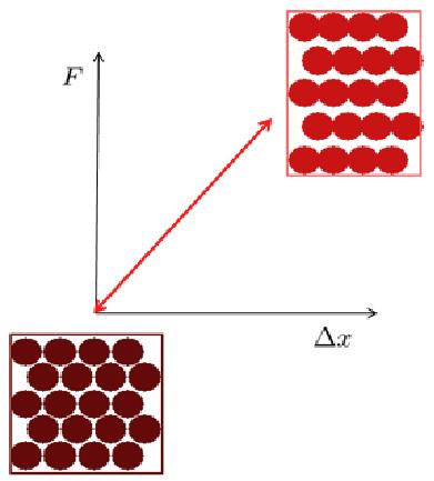
Microscopic elastic deformation corresponds to a modification in the distance between atoms under an external force, without any rearrangement of these atoms.

None
In general, it's a deformation where the distance changes proportionally to the applied force, referred to as elastic deformation.
ID:(1685, 0)
Permanent Deformation explained with Atoms
Video 
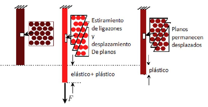
Plastic deformation means that if the applied stress is reduced, the material decreases its deformation but ends up with a permanent deformation.

None
Therefore, if it's subjected to stress again, it generally returns to its elastic form, but due to the new shape, it can't recover its original form.
ID:(1911, 0)
Bending with two Fixed Points
Unit 
One possible scenario is that a deformation force with two fixed points ($F_2$) acts on a bone with properties a body length ($L$), the modulus of Elasticity ($E$), and the moment of inertia of surface ($I_s$), which is fixed at both ends:

None
the strain energy with two fixed points ($W_2$), storing the structure against a movement in flexion with two fixed points ($u_2$), is given by
| $ W_2 =\displaystyle\frac{24 E I_s }{ L ^3} u_2 ^2$ |
the deformation force with two fixed points ($F_2$), the applied force, leads to a movement in flexion with two fixed points ($u_2$) as per
| $ F_2 =\displaystyle\frac{48 E I_s }{ L ^3} u_2 $ |
and the stress to deformation with two fixed points ($\sigma_2$), which depends on the outdoor radio ($R_2$), is expressed as
| $ \sigma_2 =\displaystyle\frac{ R_2 L }{3 I_s } F_2 $ |
ID:(740, 0)
Buckling
Code 
One possible scenario is that a deformation force in buckling condition ($F_p$) acts along the axis of the bone with properties a body length ($L$), the modulus of Elasticity ($E$), the buckling factor ($K$), the effective radius ($R$), and the moment of inertia of surface ($I_s$), inducing buckling:

None
the strain energy in buckling condition ($W_p$), is defined as
| $ W_p =\displaystyle\frac{ \pi ^4 E I_s }{2 K ^4 L ^3} R ^2$ |
the deformation force in buckling condition ($F_p$), the applied force, according to
| $ F_p =\displaystyle\frac{ \pi ^2 E I_s }{ K ^2 L ^2}$ |
and the stress to deformation in the case of buckling ($\sigma_p$), which depends on the outdoor radio ($R_2$), is expressed as
| $ \sigma_p =\displaystyle\frac{ \pi ^2 E I_s }{ K ^2 L ^2 S }$ |
ID:(741, 0)
Plastic deformation in the Solido Structure
Flux 
Plastic deformation involves atoms rearranging themselves, dissociating from existing structures, and forming new bonds that are inherently stable. However, such deformation typically entails a modification in the shape of the material.

None
Plastic deformation can ultimately lead to changes that may include catastrophic ruptures, which are permanent.
ID:(1686, 0)
Bending with one Fixed Point
Matrix 
One situation that may arise is when a deformation force with a fixed point ($F_1$) acts on a bone with properties a body length ($L$), the modulus of Elasticity ($E$), and the moment of inertia of surface ($I_s$), which is fixed at one end.

None
the strain energy with a fixed point ($W_1$), storing the structure against a stress to deformation with a fixed point ($\sigma_1$), is defined by
| $ W_1 =\displaystyle\frac{3 E I_s }{2 L ^3} u_1 ^2$ |
the deformation force with a fixed point ($F_1$), the applied force, leads to a stress to deformation with a fixed point ($\sigma_1$) as per
| $ F_1 =\displaystyle\frac{3 E I_s }{ L ^3} u_1 $ |
and the stress to deformation with a fixed point ($\sigma_1$), which depends on the outdoor radio ($R_2$), is given by
| $ \sigma_1 =\displaystyle\frac{2 R_2 L }{3 I_s } F_1 $ |
ID:(739, 0)
Bone deformation due to torsion
Html 
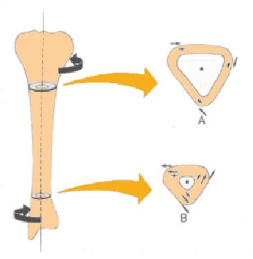
One way to cause a fracture is through bone torsion, which involves applying opposite torques at the ends:

ID:(1916, 0)
Deformación de Huesos
Storyboard 
Variables
Calculations
Calculations
Equations
As the the total Hook constant of springs in parallel ($k_p$) of the spring Hook constant i ($k_i$) is
it follows that in the case of the microscopic Hook constant ($k_m$) being equal to
$k_p = N_p k_m$
the total Hook constant of springs in parallel ($k_p$) corresponds, in this case, to the Hook's constant of a monoatomic thickness section. To obtain the constant for the entire body, one must sum all the sections in series, and for this, we work with the relationship for the sum of the total Hook constant of springs in series ($k_s$), given by
With the number of sections being equal to the number of springs in series ($N_s$), and if we assume that they are all equal, we obtain
$\displaystyle\frac{1}{k} = N_s\displaystyle\frac{1}{N_p k_m}$
meaning
$k = \displaystyle\frac{N_p}{N_s}k_m$
Finally, with the relationships for the body length ($L$) and the microscopic length of spring ($l$)
and with the body Section ($S$) and the microscopic section of spring ($s$)
we ultimately obtain
When we apply forces the force ($F$) at the ends of the springs, the springs will elongate (or compress) by the spring elongation i ($u_i$) and the spring Hook constant i ($k_i$) respectively. If the point of contact between both springs is at rest, the sum of the forces acting on it must add up to zero, meaning they must be equal to the force ($F$). Therefore, for each spring $i$, it must satisfy
$F = k_iu_i$
The total elongation will be equal to the sum of the individual elongations:
$u = \displaystyle\sum_iu_i$
And using Hooke's law, this can be expressed as:
$u = \displaystyle\sum_i\frac{F}{k_i}$
If we introduce a total constant for the case of a series connection the total Hook constant of springs in series ($k_s$), such that
$F = k_su$
Then we have:
With Hooke's Law for the elastic Force ($F_k$), the hooke Constant ($k$), and the elongation ($u$) as follows:
and the expression for the hooke Constant ($k$) in terms of the body length ($L$), the body Section ($S$), the microscopic length of spring ($l$), the microscopic section of spring ($s$), and the microscopic Hook constant ($k_m$):
combined with the expression for the modulus of Elasticity ($E$):
the result is:
Since each spring is exposed to the same applied force the force ($F$), the springs with constants the spring Hook constant 1 ($k_1$) and the spring Hook constant 2 ($k_2$) will deform by magnitudes the spring elongation 1 ($u_1$) and the spring elongation 2 ($u_2$) respectively, according to the following equations:
$F = k_1u_1$
$F = k_2u_2$
The total elongation will be the sum of both elongations:
$u = u_1 + u_2 = \displaystyle\frac{F}{k_1} + \displaystyle\frac{F}{k_2} = \left(\displaystyle\frac{1}{k_1} + \displaystyle\frac{1}{k_2}\right)F$
Therefore, the system behaves as if it had a spring constant equal to:
Since each spring can have a different spring constant, represented by the spring Hook constant i ($k_i$), the force contributed by each spring also varies. According to Hooke's law, the forces $F_i$ can be expressed as:
$F_i = k_i u$
As the total force $F$ corresponds to the sum of individual forces, we have:
$F =\displaystyle\sum_i F_i = \displaystyle\sum_i k_i u$
Therefore, a total spring constant can be defined as:
Since each spring is subjected to the same the elongation ($u$), the forces will be different if the spring constants are different. Therefore, if the spring Hook constant 1 ($k_1$) and the spring Hook constant 2 ($k_2$) are the spring constants, the forces will be:
$F_1 = k_1 u$
$F_2 = k_2 u$
As a result, the total force will be:
$F = F_1 + F_2 = k_1u + k_2u = (k_1 + k_2)u$
Thus, the system behaves as if it had a spring constant equal to:
Examples
The relationship between the elastic Force ($F_k$) and elongation the elongation ($u$) is written and referred to as Hooke's Law. The constant the hooke Constant ($k$) is called the spring constant:
If you want to model how a solid deforms under the influence of a force, you can first consider the behavior of a subunit, such as two springs connected one behind the other, as shown in the image:
This type of arrangement of the springs is called in series. It is characterized by the fact that the force the force ($F$) is the same in both springs, and they deform according to the hooke Constant ($k$). Therefore, the equivalent spring constant the elongation ($u$) is calculated as the sum of the spring elongation 1 ($u_1$) and the spring elongation 2 ($u_2$), which, in turn, by Hooke's law:
is equal to the force ($F$) divided by the constants the spring Hook constant 1 ($k_1$) and the spring Hook constant 2 ($k_2$), respectively:
$u = u_1 + u_2 = \displaystyle\frac{F}{k_1} + \displaystyle\frac{F}{k_2} = \left(\displaystyle\frac{1}{k_1} + \displaystyle\frac{1}{k_2}\right)F$
Therefore, the system of two springs can be treated as a single spring whose equivalent spring constant the total Hook constant of springs in series ($k_s$) is calculated as follows:
In the case of two resistors with values the spring Hook constant 1 ($k_1$) and the spring Hook constant 2 ($k_2$), when they are connected in parallel, they act as if there were an equivalent resistance the total Hook constant of springs in series ($k_s$) given by the following equation:
This concept can be generalized for the spring Hook constant i ($k_i$) as:
If we have two resistors with values the spring Hook constant 1 ($k_1$) and the spring Hook constant 2 ($k_2$) connected in series, the extensions add up, causing each individual resistor to act based on its inverse. In this way, the inverse of the total Hook constant of springs in series ($k_s$) is equal to the sum of the inverses of the individual constants the spring Hook constant i ($k_i$):
$\displaystyle\frac{1}{k_s}=\displaystyle\frac{1}{k_1}+\displaystyle\frac{1}{k_2}+\displaystyle\frac{1}{k_3}$
If one wishes to model how a solid deforms under the influence of a force, the behavior of a subunit can first be considered, such as two springs connected side by side, as shown in the image:
This type of arrangement of the springs is called in parallel. It is characterized because the elongation ($u$) in both springs is the same and each spring contributes the force ($F$) according to the spring Hook constant 1 ($k_1$) and the spring Hook constant 2 ($k_2$) as per Hooke's law:
Thus, it follows that:
$F = F_1 + F_2 = k_1 u + k_2 u = (k_1 + k_2)u$
Therefore, the system of two springs can be treated as a single spring whose equivalent spring constant the total Hook constant of springs in parallel ($k_p$) is calculated as follows:
In the case of two springs with constants the spring Hook constant 1 ($k_1$) and the spring Hook constant 2 ($k_2$) that can be modeled by a single spring with a constant the total Hook constant of springs in parallel ($k_p$) calculated using the following equation:
For the more general case of springs with constants ERROR:10228,0, the equation can be generalized as follows:
This allows us to model a macro structure as follows:
For the case of two resistors with values the spring Hook constant 1 ($k_1$) and the spring Hook constant 2 ($k_2$), when they are connected in parallel, they act as if there were an equivalent resistance the total Hook constant of springs in parallel ($k_p$) given by the following equation:
This concept can be generalized for the spring Hook constant i ($k_i$) as:
If you have two resistors with values the spring Hook constant 1 ($k_1$) and the spring Hook constant 2 ($k_2$) connected in parallel, their effects add up, acting as if there were an equivalent resistance the total Hook constant of springs in parallel ($k_p$) equal to the sum of the individual constants:
$k_p=k_1+k_2+k_3$
The bone can be modeled as a hollow cylinder since the material inside it is not capable of bearing a significant load. Therefore, it is geometrically modeled as a cylinder with properties the body length ($L$), the inside radio ($R_1$), and the outdoor radio ($R_2$):
Therefore, the effective radius ($R$) is
the body Section ($S$) is
and the moment of inertia of surface ($I_s$) is
Microscopic elastic deformation corresponds to a modification in the distance between atoms under an external force, without any rearrangement of these atoms.
In general, it's a deformation where the distance changes proportionally to the applied force, referred to as elastic deformation.
$k_p=Nk$
To calculate the macroscopic equivalent of the microscopic spring constant, one must sum all the microsprings both in parallel and in series. To do this, it is necessary to know the number of springs connected in parallel.
The number of springs connected in parallel can be determined with the body Section ($S$) and the microscopic section of spring ($s$). The number of springs in parallel ($N_p$) is calculated by dividing the body Section ($S$) by the microscopic section of spring ($s$):
$k_s=\displaystyle\frac{k}{N}$
To calculate the macroscopic equivalent constant of the microscopic spring constant, all microsprings must be added both in parallel and in series. To do this, it is necessary to know, in particular, the number of springs connected in series.
If we want to estimate the number of springs in series ($N_s$), it is sufficient to know the body length ($L$) and the microscopic length of spring ($l$). The number of springs in series ($N_s$) is calculated by dividing the body length ($L$) by the microscopic length of spring ($l$):
For a bar with ERROR:5355.1 and the body Section ($S$), you can calculate the number of springs in parallel ($N_p$) and the number of springs in series ($N_s$) using the microscopic length of spring ($l$) and the microscopic section of spring ($s$). With these values, you can calculate the spring constant for an entire section by multiplying by the number of springs in parallel ($N_p$) using the microscopic Hook constant ($k_m$). This way, you can calculate the hooke Constant ($k$) by dividing the obtained value by the number of springs in series ($N_s$):
$k=\displaystyle\frac{k_p}{N_s}=\displaystyle\frac{N_p}{N_s}k_m$
If you introduce the expressions for the number of elements with the microscopic length of spring ($l$) and the microscopic section of spring ($s$), you get the following expression:
The expression for the hooke Constant ($k$) given by
has two macroscopic parameters, which are the body length ($L$) and the body Section ($S$). The remaining the microscopic Hook constant ($k_m$), the microscopic length of spring ($l$), and the microscopic section of spring ($s$) are microscopic and thus depend on the material being described. Therefore, it makes sense to define these factors as the modulus of Elasticity ($E$), so that:
As Hooke's Law relates the elastic Force ($F_k$) through the hooke Constant ($k$) and the elongation ($u$) in the following manner:
you can replace the hooke Constant ($k$) with the microscopic expression and using the definition of the modulus of Elasticity ($E$), you obtain with the body length ($L$) and the body Section ($S$) that:
The elastic Force ($F_k$) is a function of the modulus of Elasticity ($E$), the body Section ($S$), the elongation ($u$), and the body length ($L$).
In this case, the ratio between the elongation ($u$) and the body length ($L$) is represented by the deformation ($\epsilon$), which can be defined as follows:
The elastic Force ($F_k$) is a function that depends on the modulus of Elasticity ($E$), the body Section ($S$), the elongation ($u$), and the body length ($L$).
Similarly, just as the deformation ($\epsilon$) is introduced to avoid using the dimension the body length ($L$), we can construct a factor that expresses the elastic Force ($F_k$) in terms of the body Section ($S$) as the strain ($\sigma$).
The Hooke's Law for ERROR:8845, ERROR:8843, and ERROR:8838 is expressed as:
This law can be generalized for the stress on axis $i$ ($\sigma_i$) and the deformation in the coordinate $i$ ($\epsilon_i$) as:
In general, the deformation ($\epsilon$) is defined as the variation of the elongation ($u$) in proportion to the body length ($L$):
This concept can be generalized in the microscopic limit, where the deformation in the coordinate $i$ ($\epsilon_i$) is introduced as the variation of displacement in i ($\partial u_i$) over the length of an element in i ($\partial x_i$) in the direction $i$, and it would be expressed as:
The reason for using a different symbol to denote the differential
$d \rightarrow \partial$
is that there are several differentials that affect different variables in the model. The use of the symbol $\partial$ indicates that one should perform one variation at a time, meaning that when considering one variable, the remaining variables are assumed to have their initial values.
In the case of shear, the deformation is not associated with expanding or compressing, but with laterally offsetting the faces of a cube. The shear is therefore described by the angle
where
With the outdoor radio ($R_2$) and the inside radio ($R_1$), the body Section ($S$) is defined as
Plastic deformation means that if the applied stress is reduced, the material decreases its deformation but ends up with a permanent deformation.
Therefore, if it's subjected to stress again, it generally returns to its elastic form, but due to the new shape, it can't recover its original form.
One possible scenario is that a deformation force with two fixed points ($F_2$) acts on a bone with properties a body length ($L$), the modulus of Elasticity ($E$), and the moment of inertia of surface ($I_s$), which is fixed at both ends:
the strain energy with two fixed points ($W_2$), storing the structure against a movement in flexion with two fixed points ($u_2$), is given by
the deformation force with two fixed points ($F_2$), the applied force, leads to a movement in flexion with two fixed points ($u_2$) as per
and the stress to deformation with two fixed points ($\sigma_2$), which depends on the outdoor radio ($R_2$), is expressed as
$T=\displaystyle\frac{I_sG}{L}\gamma$
One possible scenario is that a deformation force in buckling condition ($F_p$) acts along the axis of the bone with properties a body length ($L$), the modulus of Elasticity ($E$), the buckling factor ($K$), the effective radius ($R$), and the moment of inertia of surface ($I_s$), inducing buckling:
the strain energy in buckling condition ($W_p$), is defined as
the deformation force in buckling condition ($F_p$), the applied force, according to
and the stress to deformation in the case of buckling ($\sigma_p$), which depends on the outdoor radio ($R_2$), is expressed as
Plastic deformation involves atoms rearranging themselves, dissociating from existing structures, and forming new bonds that are inherently stable. However, such deformation typically entails a modification in the shape of the material.
Plastic deformation can ultimately lead to changes that may include catastrophic ruptures, which are permanent.
Lateral deformation is directly proportional to the deformation it causes. The proportionality coefficient is denoted as the poisson coefficient ($\nu$) [1] and typically falls within the range of 0.15 to 0.4.
If the original deformation is the deformation ($\epsilon$) and the generated one is the deformation in the direction perpendicular to the force ($\epsilon_{\perp}$), the following relationship is established:
In the linear approximation, the Poisson's coefficient represents the relationship between lateral and longitudinal deformations.
where the sign indicates that the deformation is in the opposite direction to the cause.
[1] This concept was introduced by Sim on Denis Poisson in a statistical analysis work, in which he mentioned, among other unrelated topics to mechanics, what was later referred to as the Poisson's coefficient in an elasticity example. The work is titled "Recherches sur la Probabilit des Jugements en Mati re Criminelle et en Mati re Civile" (Research on the Probability of Judgments in Criminal and Civil Matters), authored by Sim on Denis Poisson (1837).
The moment of inertia of surface ($I_s$) is calculated in the case of a cylinder with the outdoor radio ($R_2$) and the inside radio ($R_1$) through
One situation that may arise is when a deformation force with a fixed point ($F_1$) acts on a bone with properties a body length ($L$), the modulus of Elasticity ($E$), and the moment of inertia of surface ($I_s$), which is fixed at one end.
the strain energy with a fixed point ($W_1$), storing the structure against a stress to deformation with a fixed point ($\sigma_1$), is defined by
the deformation force with a fixed point ($F_1$), the applied force, leads to a stress to deformation with a fixed point ($\sigma_1$) as per
and the stress to deformation with a fixed point ($\sigma_1$), which depends on the outdoor radio ($R_2$), is given by
One way to cause a fracture is through bone torsion, which involves applying opposite torques at the ends:
ID:(322, 0)
