
Sound Propagation
Storyboard 
The propagation of sound in the ocean considers both the reflection on the surface and the ocean floor and the refractions that occur due to variations in pressure, temperature and salinity.
ID:(1550, 0)
Interpretation of sound refraction
Image
If we observe how sound varies with depth and the way it propagates:
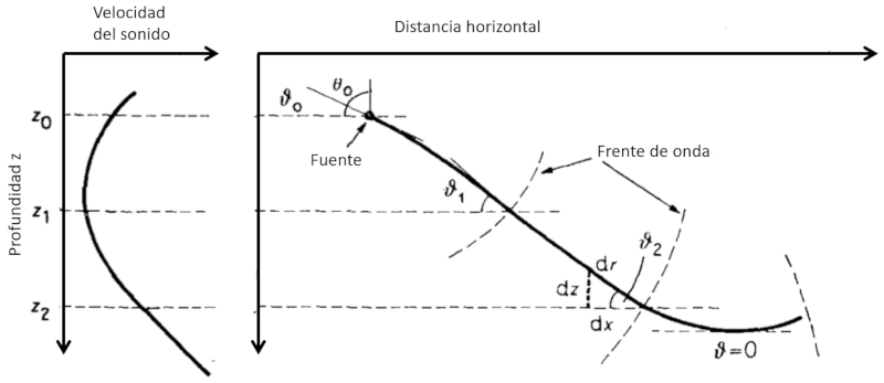
we can see that:
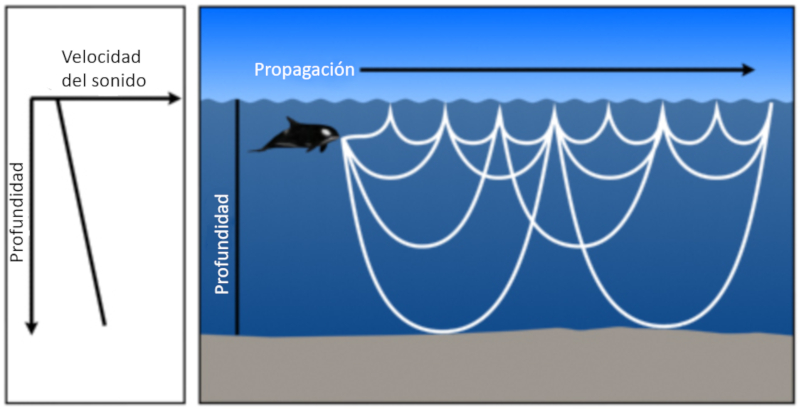
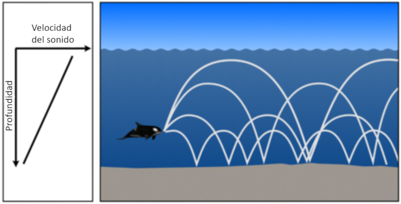
• If the speed of sound increases with depth, the angle between the beam and the horizon tends to decrease. This means that the sound will tend to decrease its descent until it becomes horizontal and, by symmetry, will continue to ascend towards the surface.
• If the speed of sound decreases with depth, the angle between the beam and the horizon tends to increase. This means that the sound will tend to increase its descent towards the bottom.
ID:(11804, 0)
If the speed of sound increases
Note
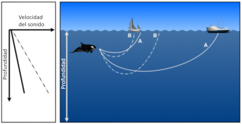
Sound emitted at a depth where the speed of sound increases with depth, the beams end up returning to the surface where they reflect and re-penetrate the medium:
ID:(11805, 0)
If the speed of sound increases and then decreases
Quote
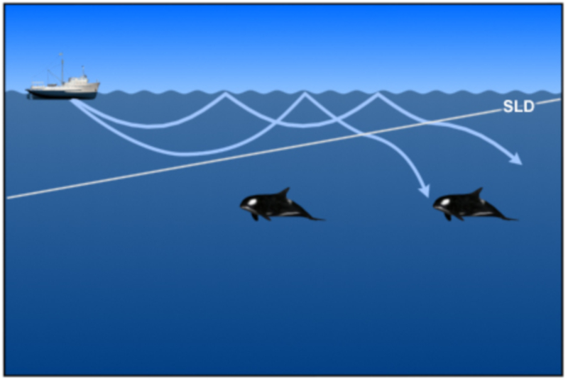
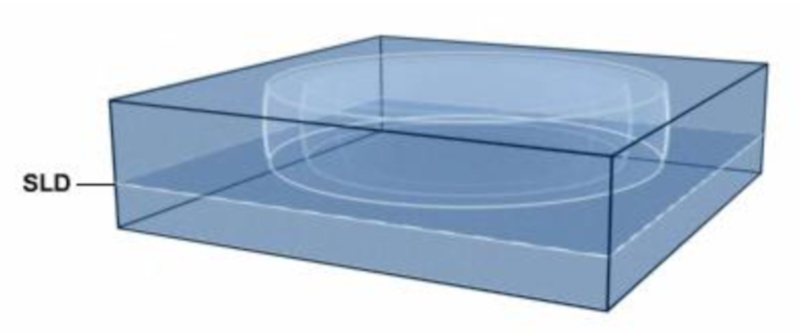
Sound emitted at a depth where the speed of sound increases with depth; the beams end up returning to the surface. However, if from a point the speed of sound is reduced, it is observed that beams with a greater angle are refracted towards the depths:
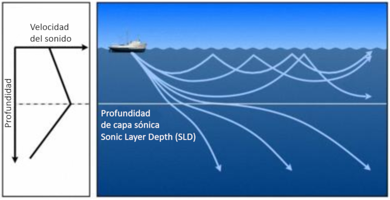
Thus an area is formed in which the beams return to the surface. This depth is called SLD sonic layer depth .
ID:(11806, 0)
Sound channel
Exercise
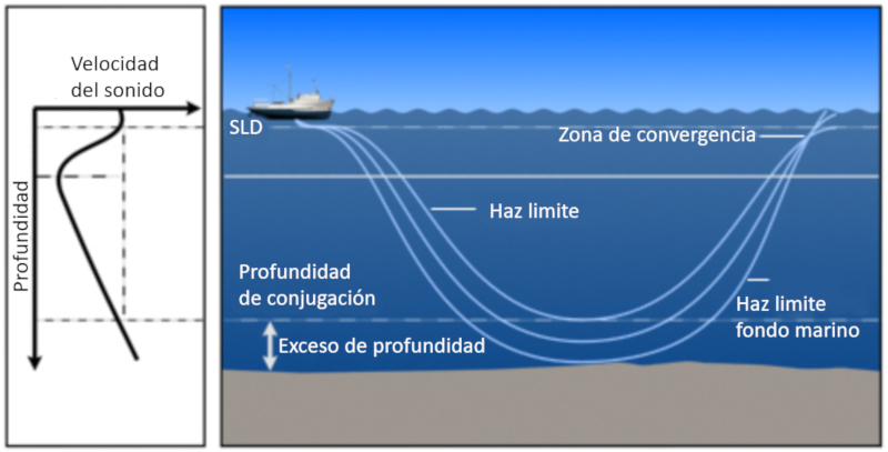
When sound diminishes and then increases again, a zone is formed where it tends to return to the area of minimum velocity. This area is called the sound channel and extends from the depth of the sonic layer depth (SLD) to a conjugate depth:
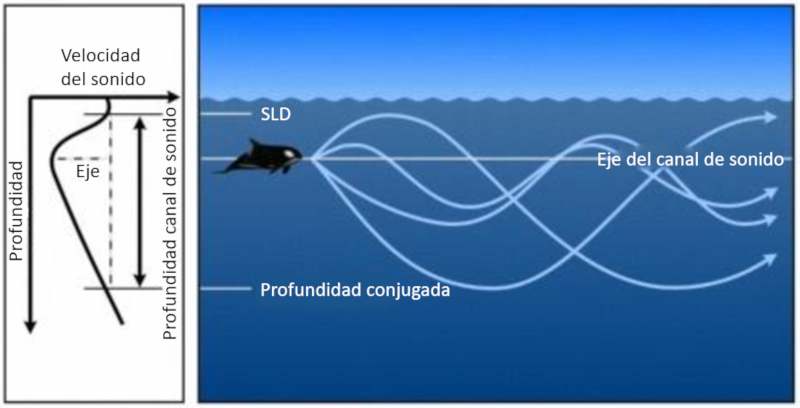
The depth at which the sound velocity reaches a minimum is called the sound channel axis.
Both propagation in the upper zone to the depth of the sound channel layer (SLD) and in the sound channel exist. However, the upper zone presents the problem that the surface dampens the sound, making the sound channel the most effective.
ID:(11807, 0)
Loss of sound in the upper layer
Equation
The sound waves that propagate over the sonic layer depth can filter to the lower zone:
ID:(11808, 0)
Shallow case with increasing speed of sound
Script
If the water is shallow and the speed of sound only increases with depth, then the sound returns to the surface either through refraction or reflection at the bottom, and then reflects off the surface:
ID:(11809, 0)
Shallow case with reduced speed of sound
Variable
If the water is shallow and the speed of sound only decreases with depth, the sound tends to go towards the bottom where it is reflected:
ID:(11810, 0)
Sound temperature and speed profile
Audio
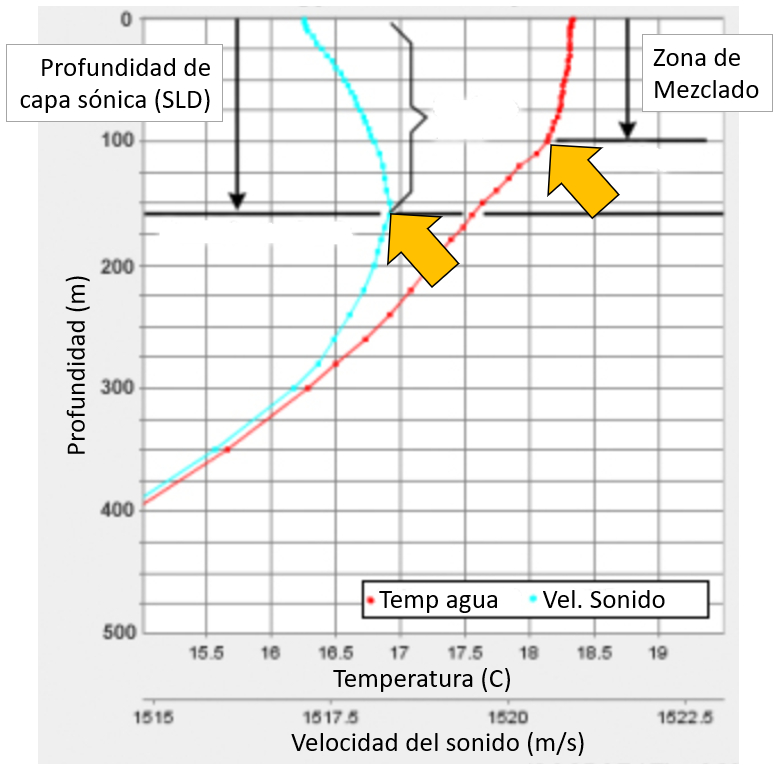
The temperature passes through a zone where it is approximately constant before descending. It remains constant in the first zone due to the turbulence generated by the wind, which tends to mix the water.
The curve of the sound velocity shows that it reaches a maximum, defining the depth of the sonic layer. At its maximum point, the depth of the sonic layer is defined:
ID:(11811, 0)
Behavior in greater depth
Video
In general, due to gravity, the speed of sound always increases with depth. When a sound beam reaches the depth of the sonic layer depth (SLD), it eventually diverges and returns to the surface. The beams that manage to return to the surface are situated between a boundary defined by reflection at the bottom and the boundary of the beam that manages to penetrate into lower layers and eventually reaches the surface:
ID:(11812, 0)
Propagation over greater distances
Unit
For sound emitted near the surface, propagation can be modeled as spherical propagation. High-frequency sound tends to dampen at greater distances, so the spherical model is sufficient. However, for low-frequency sound, it can travel throughout the basin. In this case, it moves through the upper zone to the depth of the acoustic layer (SLD) and/or through the sound channel. In both cases, the system can be modeled using cylindrical coordinates:
ID:(11813, 0)
Real sound profile
Code
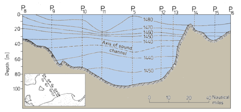
A profile of an area, such as a channel, can be obtained by plotting velocities for each depth. This enables the detection of sound channels and the depth of the sound layer:
ID:(11826, 0)
Sound Propagation
Storyboard
The propagation of sound in the ocean considers both the reflection on the surface and the ocean floor and the refractions that occur due to variations in pressure, temperature and salinity.
Variables
Calculations
Calculations
Equations
Observando la imagen se nota que los senos de los angulos son respectivamente\\n\\n
$\sin\theta_i=\displaystyle\frac{c_i\Delta t}{d}$
y\\n\\n
$\sin\theta_e=\displaystyle\frac{c_e\Delta t}{d}$
\\n\\nSi se despeja en ambas ecuaciones la distancia
$d=\displaystyle\frac{c_i\Delta t}{\sin\theta_i}=\displaystyle\frac{c_e\Delta t}{\sin\theta_e}$
por lo que se tiene que
Examples
If we observe how sound varies with depth and the way it propagates:
we can see that:
• If the speed of sound increases with depth, the angle between the beam and the horizon tends to decrease. This means that the sound will tend to decrease its descent until it becomes horizontal and, by symmetry, will continue to ascend towards the surface.
• If the speed of sound decreases with depth, the angle between the beam and the horizon tends to increase. This means that the sound will tend to increase its descent towards the bottom.
Sound emitted at a depth where the speed of sound increases with depth, the beams end up returning to the surface where they reflect and re-penetrate the medium:
Sound emitted at a depth where the speed of sound increases with depth; the beams end up returning to the surface. However, if from a point the speed of sound is reduced, it is observed that beams with a greater angle are refracted towards the depths:
Thus an area is formed in which the beams return to the surface. This depth is called SLD sonic layer depth .
When sound diminishes and then increases again, a zone is formed where it tends to return to the area of minimum velocity. This area is called the sound channel and extends from the depth of the sonic layer depth (SLD) to a conjugate depth:
The depth at which the sound velocity reaches a minimum is called the sound channel axis.
Both propagation in the upper zone to the depth of the sound channel layer (SLD) and in the sound channel exist. However, the upper zone presents the problem that the surface dampens the sound, making the sound channel the most effective.
The sound waves that propagate over the sonic layer depth can filter to the lower zone:
If the water is shallow and the speed of sound only increases with depth, then the sound returns to the surface either through refraction or reflection at the bottom, and then reflects off the surface:
If the water is shallow and the speed of sound only decreases with depth, the sound tends to go towards the bottom where it is reflected:
The temperature passes through a zone where it is approximately constant before descending. It remains constant in the first zone due to the turbulence generated by the wind, which tends to mix the water.
The curve of the sound velocity shows that it reaches a maximum, defining the depth of the sonic layer. At its maximum point, the depth of the sonic layer is defined:
In general, due to gravity, the speed of sound always increases with depth. When a sound beam reaches the depth of the sonic layer depth (SLD), it eventually diverges and returns to the surface. The beams that manage to return to the surface are situated between a boundary defined by reflection at the bottom and the boundary of the beam that manages to penetrate into lower layers and eventually reaches the surface:
For sound emitted near the surface, propagation can be modeled as spherical propagation. High-frequency sound tends to dampen at greater distances, so the spherical model is sufficient. However, for low-frequency sound, it can travel throughout the basin. In this case, it moves through the upper zone to the depth of the acoustic layer (SLD) and/or through the sound channel. In both cases, the system can be modeled using cylindrical coordinates:
A profile of an area, such as a channel, can be obtained by plotting velocities for each depth. This enables the detection of sound channels and the depth of the sound layer:
La relaci n entre los ngulos de incidencia y refractados indicados en la siguiente gr fica
se pueden escribir en funci n de la velocidad de la luz en cada medio
The refraction of sound when passing from one medium to another is generally described by Snell's law:
$\displaystyle\frac{\sin\theta_2}{\sin\theta_1}=\displaystyle\frac{c_2}{c_1}$
where $\theta$ is the angle of incidence between the normal to the surface and the beam, and $c$ are the sound velocities in mediums 1 and 2. In the case of a beam propagating through ocean water, the velocities change gradually. On the other hand, it is convenient to work with an angle $\vartheta$ of the beam with respect to the horizontal. Therefore, the law can be rewritten by replacing the sine of the angle $\theta$ with the cosine of the complementary angle $\vartheta$. If we consider a small variation of the angle and velocity as the depth increases by $dz$, we have:
$\displaystyle\frac{\cos(\vartheta + d\vartheta)}{\cos\vartheta}\sim 1-\tan\vartheta d\vartheta = 1+\displaystyle\frac{dc}{c}$
so the relationship for depth variation is:
Mientras que en el espacio el sonido se propaga en todas las direcciones reduci ndose la intensidad con la distancia al inverso del radio al cuadrado con
dentro del canal s nico lo hace en un sistema bidimensional con lo que la intensidad se reduce con la distancia a la inversa con
ID:(1550, 0)